The purpose of the present study is to verify the effectiveness of dry laser peening (DryLP), which is the peening technique without a sacrificial overlay under atmospheric conditions using femtosecond laser pulses, on the mechanical properties such as hardness, residual stress and fatigue performance of laser-welded 2024 aluminum alloy containing welding defects such as undercuts and blowholes. After DryLP treatment of the laser-welded 2024 aluminum alloy, the softened weld metal recovered to the original hardness of base metal, while residual tensile stress in the weld metal and heat-affected zone changed to compressive stresses. As a result, DryLP treatment improved the fatigue performances of welded specimens with and without the weld reinforcement almost equally. The fatigue life almost doubled at a stress amplitude of 180 MPa and increased by a factor of more than 50 at 120 MPa. DryLP was found to be more effective for improving the fatigue performance of laser-welded aluminum specimens with welding defects at lower stress amplitudes, as stress concentration at the defects did not significantly influence the fatigue performance.
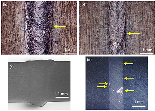
Optical microscopy images of the top and bottom rear surfaces of the laser-welded specimens are shown in Figs. 1(a) and (b). Although no cracks were observed on the surfaces, some pores existed on the top surface and some undercuts (indicated by yellow arrows in the figures) were found on both surfaces. The cross-section of the weld bead shows that full-penetration welding was achieved, where the reinforcement did not show any cracks (Fig. 1(c)). The bead widths on the top and rear surfaces were around 2.0 mm and 1.2 mm, respectively. The optical microscopy image of the bottom surface of the reinforcement-removed welded specimen is shown in Fig. 1(d), where the yellow arrows indicate the undercuts.
The results of the hardness tests for the samples with the reinforcement removed are shown in Fig. 2. Before DryLP, the hardness of the BM was 138 HV, while that on the surface of the WM was ~100 HV. It was reported that this decrease in hardness is due to i) the segregation of the strengthening elements such as magnesium, copper, and their intermetallic compounds; ii) formation and growth of non-strengthening coarse precipitates; iii) dissolution of strengthening precipitates; iv) uniform re-distribution of precipitating elements; and v) vaporization of low boiling point magnesium, during heating and the following froze due to the fast cooling rates, resulting in fewer precipitates being formed, even after natural aging for 15 months. The hardness of the HAZ in this specimen was around 130 HV (similar to the BM), because of the dissolution of precipitates and overaging. After DryLP, the hardness of all areas of the sample increased compared to that of the as-welded sample. The hardness of the WM was similar to that of the BM before peening, while the hardness of the HAZ and BM after DryLP was around 178 HV.
Residual stress curves of the top surface before and after DryLP treatment of the laser-welded specimens are shown in Fig. 3(a). The residual stress in the WM and HAZ areas of the as-welded specimen were tensile, while other areas had compressive stresses, which is a typical residual stress distribution for welded joints. This tensile residual surface stress in the WM and HAZ areas changed to compressive stress after DryLP treatment, while the magnitude of the compressive residual stresses outside these areas increased. The depth profiles of the residual stress in the WM, below the weld toe, and in the HAZ before and after DryLP treatment are shown in Fig. 3(b)(d). The tensile residual stresses in the WM, below the weld toe, and in the HAZ were observed to a depth of ~300 µm from the weld center in the as-welded specimen. These tensile residual stresses inside the material between the surface and a depth of ~100 µm changed to compressive stresses after DryLP, which is comparable to the thickness of the compressive layer in the DryLPed BM.
The results of the fatigue tests are shown in Fig. 4. The fitted curves for each specimen were obtained using Stromeyer's expression, log(σ - a) = -b log(N) + c, where σ is the stress amplitude, N is the number of cycles to failure, a, b, and c are the fitting parameters. The fatigue performances of the as-welded specimens with and without reinforcement were worse than that of the BM. Although the fatigue lives of these specimens at a stress amplitude of 180 MPa were almost the same, that of the reinforcement-removed welded specimen was shorter than that of the as-welded specimen at 120 MPa. After DryLP treatment, the fatigue performances of the specimens with and without reinforcement enhanced to a similar degree. The fatigue life increased by a factor of almost two at a stress amplitude of 180 MPa and more than 50 times at 120 MPa, which indicates that the DryLP treatment is more effective at lower stress amplitudes.
During fatigue tests, cracks initiated from undercuts at the weld toe owing to the reduced hardness and tensile residual stress remaining after welding. The fatigue performances of the as-welded specimens with and without reinforcement were comparable at a stress amplitude of 180 MPa, indicating that the stress concentration at undercuts has a greater influence on fatigue performance than stress concentration at the weld toe. The fatigue life of the specimen with the reinforcement removed was shorter than that of the as-welded specimen at a stress amplitude of 120 MPa. Small blowholes were observed in the fracture surface of the specimen without reinforcement, which were expected to influence the fatigue performance at lower stress amplitudes. Welding defects, such as undercuts and blowholes, in addition to softening or tensile residual stress, decreased the fatigue life of the welded specimens.
The fatigue performances of the specimens with and without reinforcement after DryLP treatment were improved compared to the equivalent specimens before DryLP treatment, attributed to hardening of the WM up to the value of the original BM, and the introduction of compressive residual stress. The fatigue lives of both specimens after DryLP treatment were significantly increased compared to that of the unpeened welded-specimens at lower stress amplitudes. Blowhole defects can lead to stress concentration; however, its contribution is very small as these features are generally spherical. In addition, the stress concentration at undercuts is smaller at lower stress amplitudes. Therefore, the effect of positive factors induced by DryLP, such as hardening and compressive residual stress, was larger than that of the negative factors, such as stress concentration at undercuts and blowholes at lower stress amplitudes. In addition, for gas metal arc welding lap fillet joint in GA 590 MPa steel sheets, the blowholes in WM did not significantly affect the fatigue life at relatively lower stress amplitudes, although the fatigue life decreased in the presence of blowholes and surface pores. Overall, DryLP effectively improved the fatigue performance of laser-welded specimens containing welding defects at lower stress amplitudes.