The interfacial microstructure evolution and mechanical behavior of Ti-6Al-4V/Si3N4 joints with insertion of a 2 mm-thick Nb interlayer were studied by brazing with Au96.5Ni3Ti0.5 (mass%) alloy as a heat- and corrosion-resistant filler. When the joints were brazed at 1323 K with holding times of 0, 5, and 10 min, multilayered Au4Ti, Au2Ti, AuTi, AuTi3, and Au2Nb3 intermetallic compounds were formed at the Ti-6Al-4V/Nb interface, whereas two distinct regions consisting of Au2Nb3 layer and AuNi solid solution were predominantly developed at the Nb/Si3N4 interface. Joints brazed with a 0 min holding time fractured, with initiation at the reaction-layer/Si3N4 interface and propagation into the Si3N4 with a concave morphology because of large residual stress; the joints exhibited a maximum average room-temperature bending strength of 53 MPa.
Microstructural evolution and mechanical characterization of
Nb-interlayer-inserted Ti-6Al-4V/Si3N4 joints brazed with AuNiTi filler alloy
[Published in Materials Science & Engineering A, doi.org/10.1016/j.msea.2020.139093.]
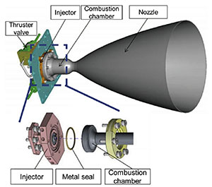
Fig. 1 Schematic of the major components in a typical spacecraft thruster. The dashed rectangular region shows the detailed assembly of the combustion chamber and injector via bolted joints. Figure reproduced courtesy of Mitsubishi Heavy Industry.
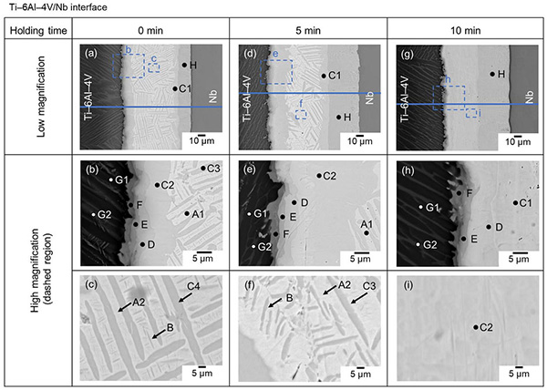
Fig. 2 Low and high-magnification images of the cross-sectional microstructures at Ti-6Al- 4V/Nb interfaces in joints brazed with different holding times. Each phase is denoted by A: Au, B: Ni, C: Au4Ti, D: Au2Ti, E: AuTi, F: AuTi3, G: Au-alloyed α+β Ti, and H: Au2Nb3.
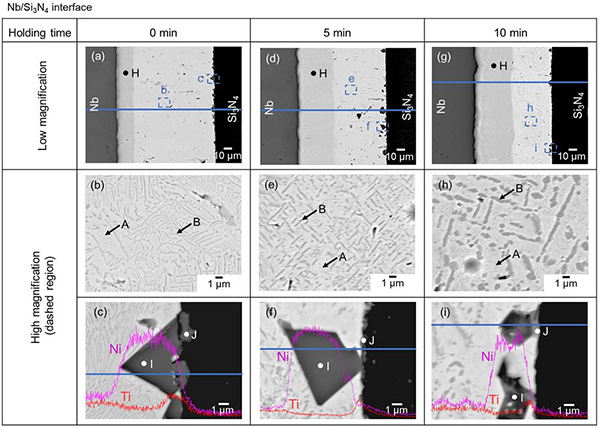
Fig. 3 Low- and high-magnifications of cross-sectional microstructures at the Nb/Si3N4 interface obtained in joints brazed with different holding times. Each phase is denoted by A: Au, B: Ni, H: Au2Nb3, I: Ni3Si, and J: TiN and Ti5Si3.
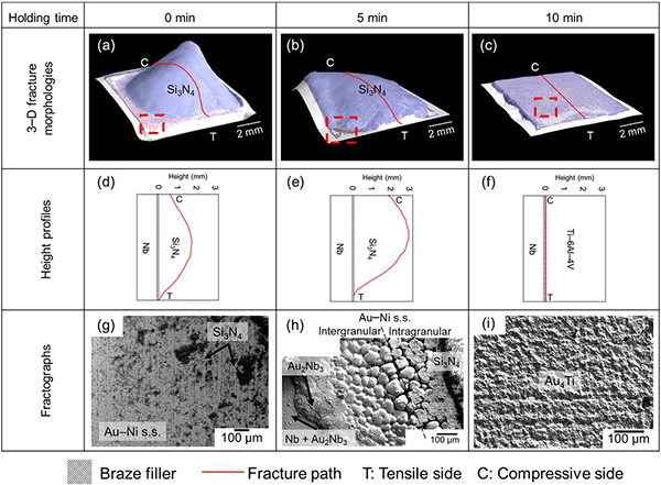
Fig. 4 (ac) Three-dimensional (3D) optical images of fracture morphologies,
(df) height profiles obtained along the solid red lines,
(gi) magnified SEI of the exposed metallic region (dashed regions in (ac))
on the Nb side of fractured joints.