1. Introduction
A 4D strain mapping technique [19], which enables the characterization of time-dependent 3D strain distributions, is employed in the present research to reveal the time-dependent 3D development of hydrogen-induced strain localization during loading and hydrogen repartitioning in the strain localization region in order to identify the microstructural features that lead to the initiation and propagation of hydrogen-induced cracks in Al-Zn-Mg-Cu aluminum alloys.
2. Materials and experimental methods
High Zn (10 % mass Zn) Al-Zn-Mg-Cu aluminum alloys were used in the present research. The chemical compositions were 10.00 Zn, 2.40 Mg, 1.50 Cu, 0.15 Zr, 0.04 Ti, 0.05 Si, 0.05 Fe and balance Al in mass%. A bulk specimen with 200 mm in length, 15 mm in width and 6 mm in thickness was cut into an isometric layer structure with a layer thickness of 0.6 mm along the thickness direction by EDM, acting as a control sample for the measurement of hydrogen content. An X-ray tomography scan was carried out without loading and then subsequent scans were performed, the step size between each scans was approximately 0.02 mm. The influence of hydrogen repartitioning on the hydrogen embrittlement behavior in Al-Zn-Mg-Cu aluminum alloys was studied by holding an applied displacement for holding times (Th) of 0.53 ks and 3.34 ks at each step.
3. Results
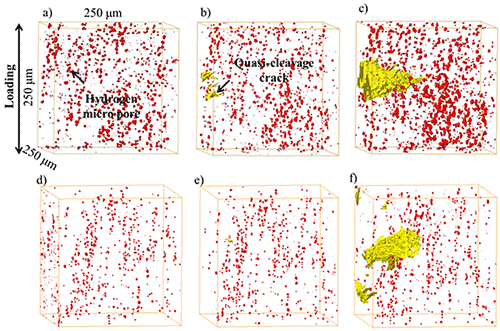
A series of 3D perspective views of hydrogen micro pores and voids near the quasi-cleavage cracks in the 10 Zn (Th=0.53 ks) specimens under different applied strains are shown in Fig. 1. The underlying intermetallic particles and aluminum matrix are not displayed. Hydrogen micro pores are distributed uniformly in the matrix, as shown in Fig. 1. Two neighboring quasi-cleavage cracks are initiated near the surface at a strain of 8.3 %, and they propagated and coalesced with an increase in the applied strain levels, as shown in Fig. 1. Growth of pre-existing hydrogen micro pores and the nucleation of voids due to the fracture of intermetallic particles are observed ahead of the quasi-cleavage crack tip at an applied strain of 12.0 %, as shown in Fig. 1. In contrast, the quasi-cleavage crack was initiated at an applied strain of 1.5 % in the 10 Zn (Th=3.34 ks) specimen, as shown in Fig. 1. The quasi-cleavage crack was initiated just after yielding was reached, and it propagated at a relatively low applied strain range from 1.5 to 5.5 %, as shown in Fig. 1. A high hydrostatic strain concentration in the strain localization region is observed, especially along the propagation path of the quasi-cleavage crack, indicating volume expansion due to the formation of vacancies in the presence of hydrogen. A comparison of the volume expansion of the measured value from the hydrostatic strain map and the calculated value with a vacancy formation energy of 0.66 eV and 0.35 eV are shown in Fig. 2. The volume expansion increases with the increase in holding time, indicating that the migration and accumulation of hydrogen in the flow localization region is time-dependent. In addition, the volume expansion increases with the decrease in the vacancy formation energy.
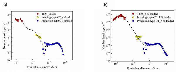
Figure 3 shows the size and number density distribution of voids under different applied strain levels. Voids observed by HAADF-STEM, imaging-type CT and projection-type CT are all applied to identify the initiation and growth of voids under loading. Due to the destruction of an oxide film, various hydrogen atoms enters the materials and become trapped at various trap sites, such as vacancies, interstitial lattices, intermetallic particles, dislocations and grain boundaries, during a casting process. According to Toda, et al., hydrogen micropores are formed during the homogenization process and remain after extensive plastic deformation, such as the rolling process. The number density of hydrogen micropores ranges from 1010 to 1012/m3, marked as blue points in Fig. 3. The number density of the newly formed nano voids is around 1019 to 1020/m3, which is ten times higher than that for the unloaded state. In addition, it can be seen that the most frequently observed size range of the hydrogen micropores is not remarkably different, only very coarse hydrogen micropores of approximately 8 µm or even larger were observed, due mainly to the growth and coalescence at the applied strain of 5 %.
4. Conclusion
Hydrogen-induced strain localization that results in premature fracture at a low applied strain is observed with the help of a 3D strain mapping technique. The hydrostatic strain concentration along the fracture surface is attributed to the initiation of vacancies and nano voids in the strain localization region during loading. Numerous internal hydrogen atoms are repartitioned at vacancies and nano voids due to their high density in the strain localization region during loading.


