The objectives of the study are to develop the high-speed biaxial stretching apparatus and to exhibit the effect of the strain-rate on the forming limit strain for thin aluminum sheets. Low- and high-speed stretching tests were performed. The order of the strain-rate varied from 10-4 to 10-1 /s in the low-speed regime. It was about 100 /s in the high-speed test, in which a drop weight drove the forming punch. The stretching forming test was carried out under various conditions in strain ratios.
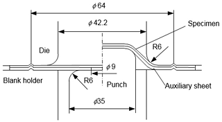
The stretch forming testing method developed by Marciniak and Kuczynski was employed, which is often called M-K method illustrated in Fig. 1. Test materials are a pure aluminum A1050 and its alloy A5052. A sheet specimen is strained by the punch with the annular auxiliary sheet. The periphery of the stacked sheets is clamped. The central portion of the specimen is free from friction because the auxiliary sheet has 9 mm diameter hole. Rosin powder was sprayed to the interface between the specimen and annular auxiliary sheet constraining the specimen by increasing the friction for avoidance of fracture around the rounded corner of the punch. On the other hand, bees wax was applied to the interface between the punch and the auxiliary sheet to promote the stretching deformation by decreasing the friction at the tool interface.
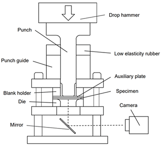
High-speed stretching apparatus illustrated in Fig. 2 was devised. It is attached to the base plate in the impact testing machine. The forming punch is driven by the drop weight. The mean strain-rate was set to about 100 /s during testing. The mass of the drop hammer was 56 kg and the impact speed was set to 3.6 m/s. The experimental condition was determined so that the punch stops immediately after fracture occurrence in the case for equi-biaxial stretching of aluminum alloy A5052. Low-speed test was also carried out using a hydraulic type deep drawing testing apparatus. The mean strain-rate ranges from 3 ![]() 10-4 to 10-1 /s. The variations in strain ratios are 1 : 1 (equi-biaxial stretching), 1 : 3, 1 : 0 (plane strain stretching) and to 1 : -0.5 (uniaxial tension). The rolling direction of the sheet specimen conforms to the major strain direction. The auxiliary sheet was a 0.8 mm thick SUS304L stainless steel sheet. The ductility of the material is larger than that of the specimen.
10-4 to 10-1 /s. The variations in strain ratios are 1 : 1 (equi-biaxial stretching), 1 : 3, 1 : 0 (plane strain stretching) and to 1 : -0.5 (uniaxial tension). The rolling direction of the sheet specimen conforms to the major strain direction. The auxiliary sheet was a 0.8 mm thick SUS304L stainless steel sheet. The ductility of the material is larger than that of the specimen.
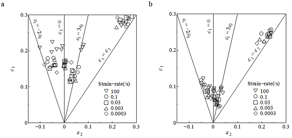
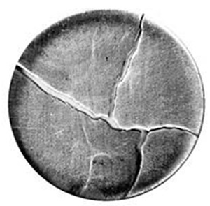
Forming limit strain is plotted in Fig. 3 for the aluminum materials. The strain of A1050 in high-speed test is remarkably larger than those in low-speed except for equi-biaxial stretching. The strain level is almost the same in low-speed range. As for the A5052, there is a tendency for the limit strain to become larger with the increase of strain-rate in low-speed regime. The difference of strain between the strain-rates of 0.1 and 100 /s is not observed. Examples of fracture appearance of A5052 specimen is demonstrated in Fig. 4. Ordinary fracture patterns with single crack after local necking are observed in most cases. There appears a multiple crack mode in the case of high-speed equi-biaxial stretching. The opposite surface of the specimen that was not sprayed is shown in Fig. 5. The photo reveals that the many localized necks followed by crack formation are generated. The strain-rate sensitivity is almost zero in low-speed deformation. That of the ultimate tensile strength changes to positive at about 100 /s. The necking direction is not determined in equi-biaxial stretching. Consequently, it is implied that the positive sensitivity induced this kind of multiple necking mode.
Examples of the profiles of the crack opening are shown in Fig. 6. The profile is smoother in low-speed compared with that in high-speed. Investigation of the effect of the strain-rate on fracture surface declared that it is flat under quasi-static condition and the dimple size and depth increase with strain-rate. Rough profile provided under high-speed stretching condition may be attributed to the emergence of such microscopic phenomenon.
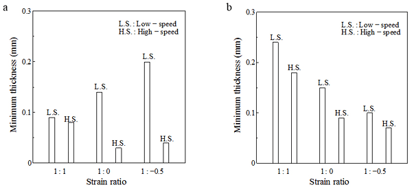
Sheet thickness at the crack is smaller remarkably in high strain-rate. The forming limit strain in high-speed is about 30 % larger than that in low-speed as shown in Fig. 3. The ductility in the necking also becomes higher. Minimum thickness at fracture edge for various conditions are summarized in Fig. 7. The data was chosen for the specimen attaining larger limit strain in each condition, because the testing condition, such as alignment of the specimen and the tools, was very properly controlled there and the fracture portion also slightly varies. Broader distinction between deformation speeds is seen in A1050 compared with that in A5052. The tendency is in good agreement with the forming limit strain for both materials. The degree of the localized thinning corresponds the maximum uniform strain or the limit strain.
