Anodic TiO2 nanotubular (TNT) films have many potential applications such as photocatalysts for decomposition of water and organic compounds, electrodes of dye-sensitized solar cells (DSSCs), electrochromic materials and biological applications. Well-ordered TNT films have been formed in the organic electrolytes containing fluorides and a small amount of water at room temperature. The faster migration of F– in comparison with O2– results in a fluoride-rich layer at the metal/oxide interface, leading to high contamination of the anodic films with fluoride and carbon species derived from the electrolyte. Therefore, the as-anodized TNT films are amorphous and post-annealing of them is indispensable for removing such impurities and crystallization of them. On the other hand, recently, TiO2 mesoporous (TMP) films were formed by anodizing of titanium in fluoride-free hot phosphate/glycerol electrolytes. The resultant films showed interesting features, for example: (i) the pore size was as small as 310 nm, regardless of the formation voltage and (ii) formation of films at an anodizing voltage of 20 V generated the crystalline anatase phase without requirement of post-annealing, whereas the films formed at less than 5 V were amorphous. In this study, we investigated the formation behavior of the TMP films on titanium during anodizing in the hot phosphate/glycerol electrolyte by cyclic voltammetry.
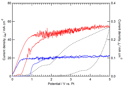
Figure 1 shows the CVs during anodizing in (a) the higher and (b) lower basic phosphate electrolytes at 433 K and (c) the fluoride electrolyte at 293 K with stirring. In the higher basic phosphate electrolyte, the current density began to increase at 30.5 V vs. Pt and became nearly constant above 1.5 V vs. Pt during the positive potential sweep. Interestingly, similar high current density was maintained even in the negative potential sweep from 5 till 31 V vs. Pt. In contrast, the current decreased markedly when anodic potential sweep was reversed at 5 V vs. Pt in the fluoride electrolyte (Fig. 1c). The current decrease is associated with the reduction of the electric field strength in the barrier layer present beneath the porous layer, being typical in anodizing of valve metals.23,24 The CV curve similar to the higher basic phosphate electrolyte is also observed in the lower basic phosphate electrolyte (Fig. 1b), although the constant current density between 1 and 5 V vs. Pt in the lower basic phosphate electrolyte is much lower than that in the higher basic phosphate electrolyte. The basicity-dependent current suggests that the concentration of OH– ions influences largely the growth rate of the TMP film.
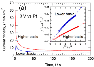
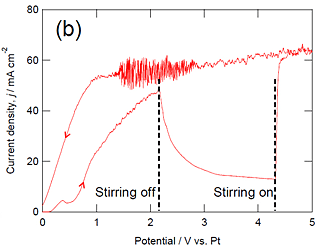
Figure 2a shows the current transient of titanium during anodizing at 3 V vs. Pt in the higher and lower basic phosphate electrolyte at 433 K without stirring. The current decreases gradually with anodizing time as in our previous papers. In the Cottrell plot shown in the inset of Fig. 2a, the reciprocal of current density is approximately proportional to the square root of time, suggesting that the observed current is diffusion-controlled. The slope in the lower basic phosphate electrolyte is approximately twice that in the higher basic electrolyte. This means from the Cottrell equation that the concentration of the diffusing species in the bulk electrolyte is twice higher in the higher basic phosphate electrolyte in comparison with the lower basic phosphate electrolyte. This is consistent with the almost twice higher steady-state current in the higher basicity phosphate electrolyte compared with the lower basicity phosphate electrolyte shown in Fig. 1. When stirring of the electrolyte stopped during potentiodynamic anodizing in the higher basic electrolyte, the anodic current turned to decrease with time (Fig. 2b), confirming the importance of supply of reactive species in electrolyte to the specimen surface. The anodic current density in the lower basic electrolyte also decreased by stopping of stirring.
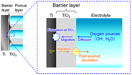
Figure 3 shows a schematic illustration during the anodic process at the pore base. When TMP films are formed by anodizing, the oxide is formed at the Ti/TiO2 interface and field-assisted dissolution occurs at the pore base, i.e., the oxygen sources such as OH– and H2O diffuse in the electrolyte, migrate in the barrier layer of the anodic TiO2 film and react with Ti metal at the Ti/TiO2 interface, whereas Ti4+ ions migrate in the barrier layer and go into the electrolyte by field assisted dissolution at the TiO2/electrolyte interface of the pore base. Form Fig. 2a, the current density at 3 V vs. Pt during anodizing was diffusion current, suggesting that the RDS was the diffusion of the oxygen sources. In addition, from Fig. 1, the diffusion current density at more than 1.5 V vs. Pt decreased with a decrease in the electrolyte basicity, implying that the oxygen source to form TiO2 may be hydroxide ions.
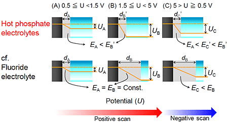
Figure 4 shows schematic illustration during the potentiodynamic anodizing in the hot phosphate electrolytes and the fluoride electrolyte. In the case of the positive sweep at less than 1.5 V vs. Pt, the barrier layer thickness dA increased with increasing the applied voltage UA in the both electrolytes (Fig. 4A). However, in the case of the positive sweep at more than 1.5 V vs. Pt, the film growth behavior in the hot phosphate/glycerol electrolytes was drastically different from that in the fluoride electrolyte. In anodizing in the fluoride electrolyte, the barrier layer thickness dB of TNT is proportional to formation potential UB. Therefore, the electric filed strength EB at the barrier layer is constant during the positive sweep. However, when the direction of the potential sweep changed from positive to negative, the electric field strength EC at the barrier layer decreased (Fig. 4B), leading to a drastic decrease in current density. On the other hand, in anodizing in the hot phosphate/glycerol electrolyte, the current density did not decrease even in the negative sweep, implying that the ion migration in the barrier layer did not control the anodizing kinetics. These results suggested that the barrier layer thickness dB’ was low and did not increase with increasing the applied potential UB’ in the hot phosphate/glycerol electrolytes (Fig. 4B), in contrast to a continuous increase in barrier layer thickness in the fluoride electrolyte during the positive sweep. Highly enhanced field-assisted dissolution at the pore base in the hot phosphate/glycerol electrolytes containing very low water concentration probably impedes the thickening of the barrier layer. Consequently, the RDS of the film growth was not migration process in the quite thin barrier layer but diffusion process of the oxygen sources in the hot phosphate electrolytes.
