The main purpose of the present study was to investigate the interfacial microstructure and its formation mechanisms along the weld bead during the traverse of the tool in lap joints of A3003 aluminum alloy and SUS 304 stainless steel lap joints. The microstructural investigation at the exit hole left after welding tool extraction and the end of the weld bead was performed using transmission electron microscopy (TEM) in combination with tensile tests.
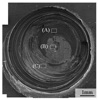
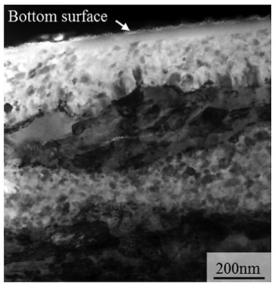
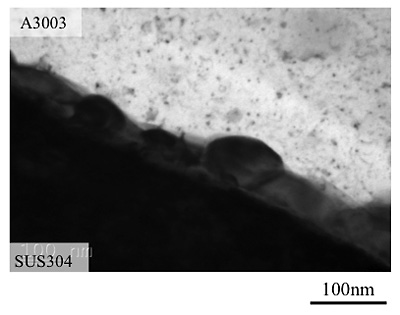
The tensile strength of the vertically sliced joint was measured to be 69 ± 5 MPa, lower than that of the A3003 base material (127 ± 2 MPa). The specimen after tensile test showed that the fracture extended only partially into the aluminum alloy, showing that the central region of the test sample is stronger than the A3003 base material. The realization of a strong joint, especially at the central region of the weld bead, given that the fractures occurred inside the base aluminum alloy. Microstructural observations were conducted by TEM at the exit hole (Fig. 1) to reveal the early stages of interface formation upon tool transit. Natural oxide layers were completely removed from the interface at the strongly joined region, and this region exhibited a100-150 nm-thick reaction layer comprised of an IMC (Fig. 2).
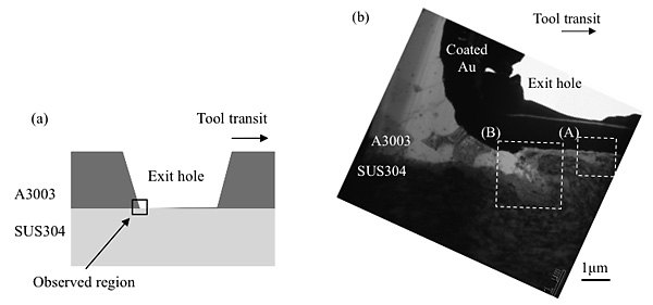
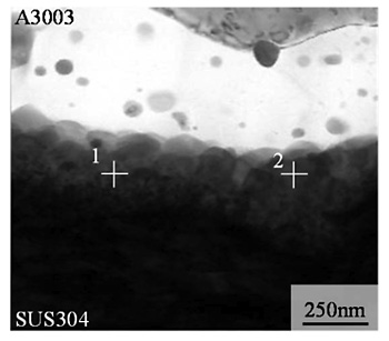
Several mixed reaction layers consisting of the ultrafine IMC and stainless steel were observed near the edge of the exit hole (Fig. 3). Additionally, exclusively stirred aluminum alloy flowed continuously into this mixed reaction layer upon tool traverse, contributing to the joining between the aluminum alloy and stainless steel. Figure. 4 shows the interface right after tool transit in region (B) from Fig. 3 (b), in which we can see a reaction layer between the aluminum alloy and stainless steel.
Given the heat generated by friction caused by the tool, the IMC became more minute. An interface stronger than the base aluminum alloy was thus obtained owing to the formation of a continuous thin reaction layer as shown in Fig. 5.