Joint Interface Microstructure of A4045/A3003/A4045 Alloy Clad Strips
Fabricated by Vertical-type Tandem Twin-roll Casting
Ryoji Nakamura1), Yuichi Tanaka1), Toshio Haga2), Yohei Harada1) and Shinji Kumai3)
1) Department of Materials Science and Engineering, Tokyo Institute of Technology
2) Department of Mechanical Engineering, Osaka Institute of Technology
3) Department of Metallurgy and Ceramics Science, Tokyo Institute of Technology
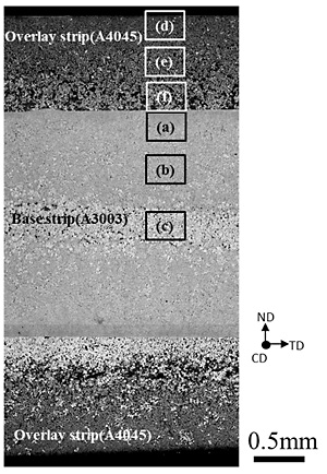
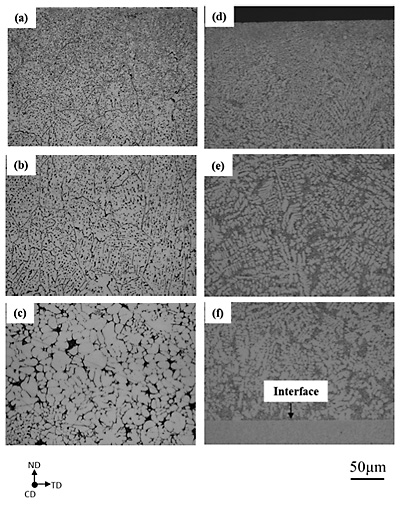
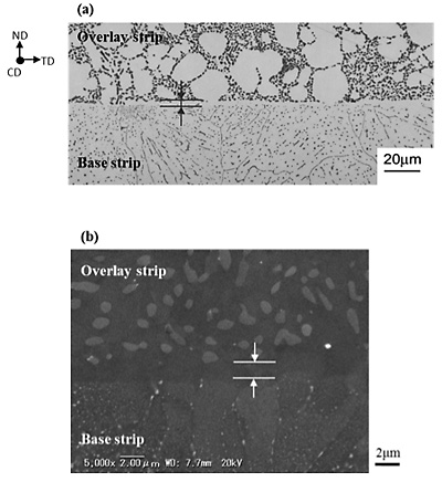
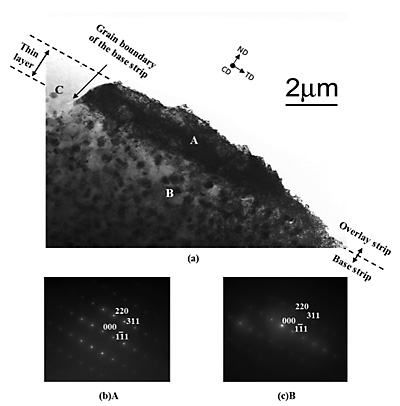
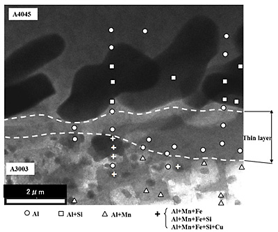
The vertical-type tandem twin-roll casting method was applied to produce a clad strip from molten alloys by single step. Figure 1 shows a schematic illustration of the vertical-type tandem twin-roll caster. The caster consisted of two twin roll casters arranged vertically. The base strip produced at the upper caster was introduced to the roll gap of the lower caster. The solidifying shell of the overlay alloy grown from the roll surface of the lower caster sandwiched the base strip and produced the clad strip. In the present study, the three-layered aluminum alloy clad strip of A4045/A3003/A4045 was fabricated. Microstructure observation and composition analysis under various magnifications from the optical microscopic- to transmission electron microscopic-order were performed. Figure 2 shows optical micrograph (OM) of the cross section of three layered clad strip. Figure 3 shows magnified SEM images of the framed areas in Fig. 2. SEM observations found fine solidification structure of both alloy strips. The joint interface was flat and no alloyed region was observed at the interface as shown in Fig. 2. Figure 4 shows (a) OM and (b) magnified SEM images of the interface between the base strip and overlay strip. A thin layer of about 1 µm in thickness including neither Al-Mn base nor eutectic Si particles, was observed at the joint interface. Figure 5 shows orientation analysis of the interface. Figure 6 shows EDS analysis using an STEM bright field image. Orientation analysis and chemical composition measurement using TEM and STEM-EDS revealed that the crystal orientation of thin layer took over that of each grain of A3003, and the composition was comparable to the α-Al matrix of A4045. This indicates that the thin layer was the solidified shell of A4045 grown from the strip surface of A3003.
[Published in Journal of Japan Foundry Engineering Society, Vol. 86, No. 3 (2014) pp. 223-228]
|
|
| Fig. 1 Schematic illustration of vertical-type tandem twin-roll caster. |
|
|
Fig. 2 Optical micrograph of cross section of three layered clad strip.
|
|
|
Fig. 3 Magnified SEM images of framed areas in Fig. 2.
Base strip: (a) surface region, (b) region between the surface and interface (c) region near the interface.
Overlay strip: (d) surface region, (e) region between the surface and interface (f) region near the interface.
|
|
|
Fig. 4 (a) OM and (b) magnified SEM images of the interface
between the base strip and overlay strip.
|
|
|
Fig. 5 Orientation analysis of the interface. (a) TEM bright field image,
(b) diffraction pattern of the thin layer, (c) diffraction pattern of the base strip.
|
|
|
Fig. 6 EDS analysis using an STEM bright field image.
|