Aircraft structures are primarily made of aluminum alloys such as A2024-T3 and A7075-T6, which have a greater springback tendency than steel. Therefore, it is necessary to develop simulation technologies to predict springback. In this study, two examples of applying simulation technologies to main aircraft plastic forming methods are investigated. One is hydro-pressure forming which can reduce the number of dies by applying hydraulic pressure with the use of a rubber pad. The other is stretch forming in which a desired shape is obtained by stretching a sheet over a tool. The purpose of this study is to improve the simulation accuracy using the finite element method (FEM). To investigate the optimal simulation parameters considering the springback, forming tests were conducted. The FEM analysis results were compared with the experimental forming data and theoretically calculated results to investigate their accuracy.
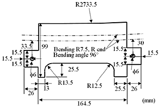
To investigate the optimal simulation parameters considering springback deformation, hydro-pressure forming tests were conducted. These tests were performed using sheets of A6013-T4 with a thickness of 1.27 mm. Specimen is shown in Fig. 1. Specimens were placed on the die. The specimen and die were fixed in place using pins, and a thick rubber sheet was placed over the specimen. They were set in the chamber, and then a pressure of up to 50 MPa was applied. The angle of each specimen after springback was measured using a protractor.
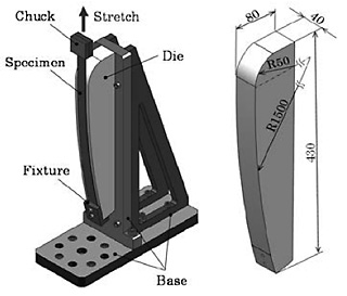
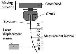
A stretch forming experiment was conducted. Tests were performed using sheets of A2024 clad in the T3 condition with a thickness of 1 mm. Specimens were rectangular sheets with a length of 500 mm and width of 25 mm. The experimental apparatus and mold are shown in Fig. 2. The die with a radius of curvature of 1,500 mm in the tensile direction was applied. After forming, specimens were fixed to the chucks of the universal tensile test machine. Shape measurement was conducted using a laser displacement meter as shown in Fig.3.
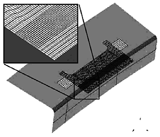
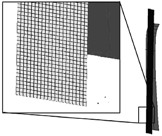
The hydro-pressure forming FEM simulation was performed using a commercial FEM package, Msc. Marc 2005. Fig. 4 shows the mesh shape and generation method of the hydro-pressure forming simulation. The static implicit method was applied. Two types of four-node shell elements were selected: a bilinear discrete Kirchhoff theory element and bilinear Mindlin element. A basic stretch forming FEM simulation was performed. Gravitational deformation was considered in the basic stretch forming FEM analysis. Fig. 5 shows the mesh shape and generation method.
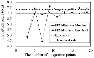
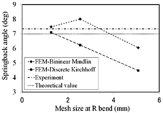
In the case of hydro pressure forming, Fig. 6 shows the amounts of springback for the different integration point numbers in the through thickness direction with the mesh size of 1.25 mm. As the number of integration points increases, the springback angles of the FEM analysis come close to the experimental and theoretical values. The springback angles for more than nine points are in good agreement with the experimental and theoretical values. The difference in shell elements is not considered to have much impact on the simulation accuracy. Fig. 7 shows the amounts of springback for the different mesh sizes at the R end in a case where the number of integration points is 19. As the mesh size decreases, the springback angles of the FEM analysis come close to the experimental and theoretical values.
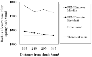
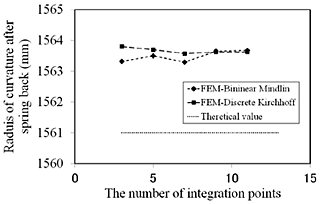
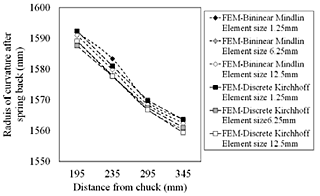
In the case of stretch forming, Fig. 8 shows the curvature radius after springback for the case with 19 integration points in the through-thickness direction with a mesh size of 1.25 mm. In Fig. 8, the experimental and theoretical values are included for comparison. The curvature radius in the experiment after springback ranges from approximately 200 to 250 mm larger than that of the mold. On the other hand, the curvature radius of the FEM analysis is approximately 50-100 mm larger. Although the FEM results do not match the experimental results, they are in good agreement with the theoretical value. Fig. 9 shows the curvature radius of the stretch forming FEM at the areas where the distances from the chuck are 245, 295, and 345 mm for the different integration point numbers in the through-thickness direction with a mesh size of 1.25 mm. The effects of the number of integration points have not been recognized in stretch forming simulations. The curvature radius of the stretch test FEM analysis at various mesh sizes is shown in Fig. 10. The tendency for the curvature to vary with decreasing mesh size was not recognized.
As conclusions, in the hydro-pressure forming, the simulation results for the bending flange springback angles were in good agreement with the experimental and theoretical values. The strongest factors influencing the springback were the number of integration points in the through-thickness direction and the mesh size at the R bend. In stretch forming, although the simulation results matched the actual values from a qualitative standpoint, it was difficult for the simulation to conform to the actual values quantitatively. The number of integration points in the through-thickness direction and the mesh size did not affect the simulation accuracy.