Recently, the severe plastic deformation processes, such as Accumulative Roll Bonding (ARB), High Pressure Torsion (HPT), Equal Channel Angular Pressing (ECAP) and etc. were developed and have made it possible to fabricate ultra-fine grained Aluminum alloys with the average diameter of several hundred nm. In conventional grain sized aluminum alloys, it is experimentally known that the yield stress changes in proportion to the -1/2 power of the average grain size with the Hall-Petch relationship. However, it is also reported that the finer grained aluminum indicate the significantly larger 0.2% proof stress (![]() 0.2) than the stress calculated by extrapolating the equation. In this manner, because the ultra-fine grain material shows various unique mechanical phenomena, the behavior of the dislocation is expected to be different from that in the conventional grain material and however the details is still unclear. In this study, the behavior of the dislocation, especially, the multiplication of dislocation during tensile test was studied.
0.2) than the stress calculated by extrapolating the equation. In this manner, because the ultra-fine grain material shows various unique mechanical phenomena, the behavior of the dislocation is expected to be different from that in the conventional grain material and however the details is still unclear. In this study, the behavior of the dislocation, especially, the multiplication of dislocation during tensile test was studied.
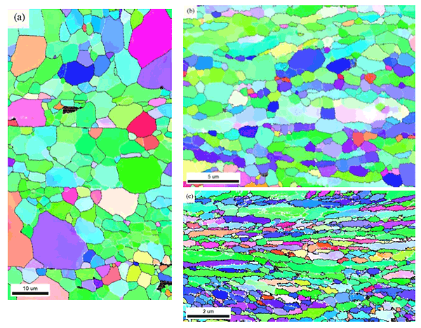
In this study, the ultra-fine grained (UFG) aluminum with the grain size of 260nm was fabricated by annealing at low-temperature for the severely plastic deformed A1100 alloy. The ARB samples were annealed at different temperatures by one- or two-step processes to change the grain size at three levels. Figures 1 show the EBSD maps of the UFG aluminum, the fine-grained (FG) aluminum with the grain size of 960nm and the coarse-grained (CG) aluminum with the grain size of 4.47![]() m. The dislocation density during the tensile deformation was investigated by the in-situ XRD measurement using SPring-8. The in-situ measurements of the dislocation density change with the progress of tensile deformation were carried out at BL19B2 in SPring8 synchrotron radiation facility. The energy of X-ray is 25keV and the beam size of incident X-ray is 3mm width and 110
m. The dislocation density during the tensile deformation was investigated by the in-situ XRD measurement using SPring-8. The in-situ measurements of the dislocation density change with the progress of tensile deformation were carried out at BL19B2 in SPring8 synchrotron radiation facility. The energy of X-ray is 25keV and the beam size of incident X-ray is 3mm width and 110![]() m height.
m height.
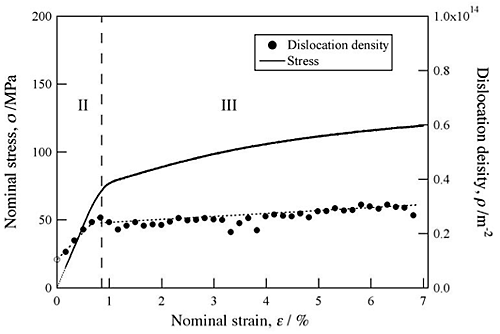
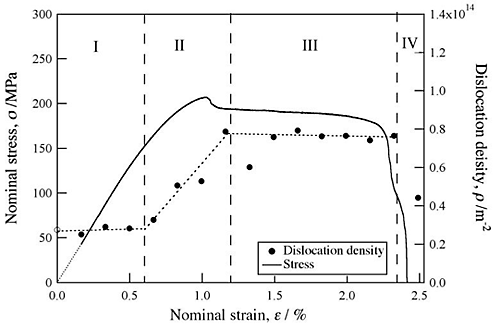
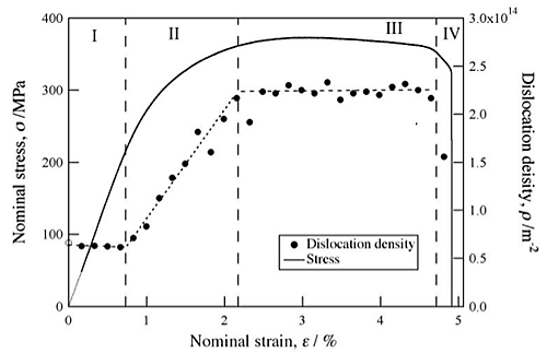
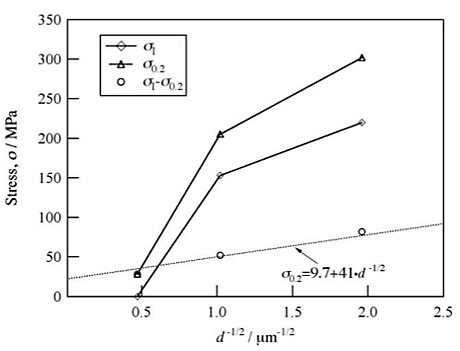
The dislocation density changed in four stages with increase in strain. Only in the CG aluminum as shown in Fig.2, the first stage was hardly observed and the stress in which the dislocation began to multiple (![]() I) was almost 0MPa. On the other hand, in UFG aluminum as shown in Fig.4, the dislocation density hardly changed from the deformation start to 0.75% strain and
I) was almost 0MPa. On the other hand, in UFG aluminum as shown in Fig.4, the dislocation density hardly changed from the deformation start to 0.75% strain and ![]() I is 220 MPa. This first stage is considered to the elastic deformation region. In the second stage, the dislocation density rapidly increased to the dislocation density,
I is 220 MPa. This first stage is considered to the elastic deformation region. In the second stage, the dislocation density rapidly increased to the dislocation density, ![]() II in which plastic deformation became possible at constant strain rate. The
II in which plastic deformation became possible at constant strain rate. The ![]() II become higher with the decrease of the grain size. In the third stage, the change became moderately. In the four stage, the dislocation density rapidly decreased by the fracture of test pieces. The amount of rapid decrease became larger with the decrease of the grain size. Additionally, as shown in Fig.5, the
II become higher with the decrease of the grain size. In the third stage, the change became moderately. In the four stage, the dislocation density rapidly decreased by the fracture of test pieces. The amount of rapid decrease became larger with the decrease of the grain size. Additionally, as shown in Fig.5, the ![]() 0.2-
0.2-![]() 1 were followed the conventional Hall-Petch relation (
1 were followed the conventional Hall-Petch relation (![]() 0.2=9.7+41d-1/2) regardless of grain size. This result imply that the conventionally-reported Hall-Petch curve for a pure aluminum were not the grain-size dependence of
0.2=9.7+41d-1/2) regardless of grain size. This result imply that the conventionally-reported Hall-Petch curve for a pure aluminum were not the grain-size dependence of ![]() 0.2 but that of
0.2 but that of ![]() 0.2-
0.2-![]() 1.
1.
