In the production of cups or containers by conventional deep drawing, the limiting drawing ratio obtained during the first drawing is very minimal. Therefore, to make deep cups, redrawing or ironing in one or more subsequent stages is necessary. An innovative method of producing very deep cups using a developed blank was previously proposed by these authors.
In this method, the drawing resistance of the blank is significantly reduced; consequently, deep cups can be obtained at the first drawing. However, the drawn cup has seams in the side wall. To make an airtight cup, the seams must be joined. In this study, a new method of forming deep cups by using the developed blank was investigated. As shown in Fig. 1, the developed blank is drawn with a punch, and friction stir welding (FSW) is conducted simultaneously to join the seams formed in the side wall.
FSW is a relatively new solid state joining process. The basic concept of FSW is very simple. A rotating tool with a specially designed probe and shoulder is inserted into the abutting edges of the sheets or plates to be joined. The tool traverses along the line of the joint. As a result, a solid state joint is produced. In this study, a rotating tool is put on the flange contact point and friction heat is generated to join the seam parts. The experimental results show that the production of a very deep and airtight cup in a single process can be successfully accomplished with the proposed method.
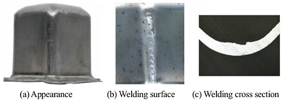
The joining properties depend on the material. In this study, soft aluminum sheet (A1050P-O, t=1.0 mm) was used for the experiments. The mechanical properties are shown in Table 1. The dimensions of the specimen are shown Fig. 2 (a). Dimension W was varied from 17 mm to 21 mm in 1 mm increments. Fig. 2 (b) shows the relative positions of point C and point D. In this study, W and distance rc - rd are very important parameters that can determine the success or failure of the processing. Fig. 3 shows an example of the forming and the welding result. The processing conditions were W=19 mm, rc - rd = 0.9 mm. Defects were not found in the welds, and the forming was good. Therefore, the resulting product was satisfactory. Fig. 4 shows the variation of joint strength according to the welding conditions. In the case of W = 18 mm, the welding strength was weak for both rc - rd = 0.5 and rc - rd = 1.5 mm. In the case of W =19 mm and W =20 mm for many rc - rd values, the welding strength was greater than the base metal strength.
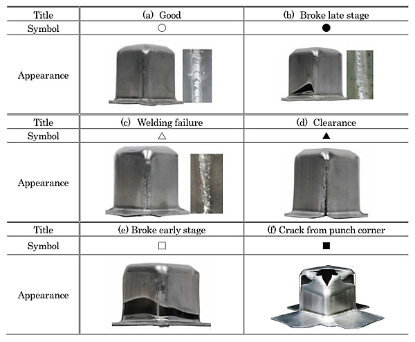
Table 2 summarizes the results obtained by various processing conditions. Each symbol has the following meaning. Symbol ![]() indicates the result was a good product. Symbol
indicates the result was a good product. Symbol ![]() indicates the product broke at a later stage of the processing. Symbol
indicates the product broke at a later stage of the processing. Symbol ![]() indicates a welding failure occurred. Symbol
indicates a welding failure occurred. Symbol ![]() indicates that clearance occurred between the flanges. Symbol
indicates that clearance occurred between the flanges. Symbol ![]() indicates the product broke at an early stage of the processing. Symbol
indicates the product broke at an early stage of the processing. Symbol ![]() indicates cracks occurred from the corner of the punch, and the product broke. Fig. 5 shows the effect of the flange width W and the value of rc - rd on the forming and welding results. The symbols in the figure have the same meaning as those in Table 2.
indicates cracks occurred from the corner of the punch, and the product broke. Fig. 5 shows the effect of the flange width W and the value of rc - rd on the forming and welding results. The symbols in the figure have the same meaning as those in Table 2.
The conclusions of this study are as follows. (a) In the drawing process using the developed blank W = 17 mm, clearance occurred between the flanges. Therefore, even in the drawing process with friction stir welding, the clearance prevented good welding. (b) When the tool center position D was located outside the flange contact point P (rc-rd ![]() 0), clearance occurred at the junction and prevented good welding. (c) For good forming and welding to the joint portion of the flange, the most suitable flange width W was 18 mm to 20 mm. The most suitable distance of the flange contact point between C and tool center position D was 0< rc - rd < 2 mm. (d) When rc - rd > 2 mm, the drawing resistance was too large, so breakage occurring early in the process prevented forming.
0), clearance occurred at the junction and prevented good welding. (c) For good forming and welding to the joint portion of the flange, the most suitable flange width W was 18 mm to 20 mm. The most suitable distance of the flange contact point between C and tool center position D was 0< rc - rd < 2 mm. (d) When rc - rd > 2 mm, the drawing resistance was too large, so breakage occurring early in the process prevented forming.