High-power electronic devices generate a large amount of heat, which degrades their performance. In particular, the demand for high-thermal-conductivity (high-TC) heat sinks for application in LEDs and power controls is increasing. However, the conventional heat-sink materials cannot prevent the degradation of temperture of thse devices because of their limited TCs. The excellent TCs and coefficients of thermal expansion (CTEs) of high-performance composites make them promising candidates for replacing conventional heat-sink materials. Carbon-reinforced pure-aluminum-matrix (C/Al) composites are attractive materials because they are lightweight and show high TCs. Although many high-TC C/Al composites have previously been developed, using them practically is difficult because they show low workability and are expensive. High-TC carbon fibers (CFs) are commercially available; however, they have never been industrially applied because they are expensive and problematic to manufacture. Casting methods such as high-pressure infiltration enable highly formable metal-matrix composites (MMCs) to be efficiently fabricated; however, it is very expensive. Low-pressure infiltration, on the other hand, is less expensive than high-pressure infiltration and can be used to produce good-quality MMCs. Carbon nanofibers (CNFs), vapor-grown carbon fibers (VGCFs), and vapor-grown carbon nanofibers (VGCNFs) are cylindrical nanostructures whose graphene layers are arranged as stacked cones, cups, and plates, respectively. VGCFs and their smaller counterparts VGCFs are among various short carbon fibers, which have recently attracted much attention for their potential thermal, electrical, and mechanical property enhancements. They are becoming increasingly used in various composites owing to their exceptional properties and low cost. However, their composites do not show superior properties because their short fibers are discontinuous. Casting high-performance, high-TC VGCF/Al composites requires a continuous VGCF preform carbon lattice and bridging between the VGCFs. Mesophase pitch (MP) is used as a crosslinker. As-received MP is produced from petroleum, so it contains numerous impurities. Therefore, MP must be heated to purify it and improve its crystallinity. In this study, we measured the lattice spacing of the (002) plane of as-received and heated MP specimens and the MP bridging between VGCFs to determine how heating affected MP crystallization and how the VGCFs affected the MP-bridging between the VGCFs used to fabricate VGCF preforms.
Starting materials used was 150-nm-diameter, 10![]() 20-
20-![]() m-long VGCFs (Showa Denko Co., Japan) and as-received 2-
m-long VGCFs (Showa Denko Co., Japan) and as-received 2-![]() m-diameter MP microparticles (JFE Chemical Co., Japan) containing
m-diameter MP microparticles (JFE Chemical Co., Japan) containing ![]() 80% carbon. The MP was subsequently heated at 793 K for 1 h under vacuum below 40 Pa to determine how heating affected MP crystallization. Then, a 1:9 mixture of VGCFs and MP was then blended for 1800 s in ethanol, which was subsequently evaporated. The molded mixture was then heated at 793 K for 1 h under vacuum below 40 Pa to fabricate the porous VGCF-MP composite preform containing 35%. The preform microstructures, the structures of the VGCF surface and the interface between the VGCFs and MP were observed using SEM and TEM. The nanostructures of the VGCF surface were analyzed using a fast fourier transform (FFT) and an inverse fast fourier transform (IFFT) by Digital Micrograph software.
80% carbon. The MP was subsequently heated at 793 K for 1 h under vacuum below 40 Pa to determine how heating affected MP crystallization. Then, a 1:9 mixture of VGCFs and MP was then blended for 1800 s in ethanol, which was subsequently evaporated. The molded mixture was then heated at 793 K for 1 h under vacuum below 40 Pa to fabricate the porous VGCF-MP composite preform containing 35%. The preform microstructures, the structures of the VGCF surface and the interface between the VGCFs and MP were observed using SEM and TEM. The nanostructures of the VGCF surface were analyzed using a fast fourier transform (FFT) and an inverse fast fourier transform (IFFT) by Digital Micrograph software.
Fig. 1 shows the XRD patterns for the as-received VGCFs and MP, and Table 1 lists the (002)-plane lattice spacings for the carbon materials and preform and the full widths at half maximum (FWHMs) of the XRD peaks for the same. The FWHM and (002)-plane lattice spacing of the as-received VGCFs were 0.53 and 0.3411 nm, respectively. Moreover, the peak attributed to the (002) plane of the as-received MP was broad; the FWHM and (002)-plane lattice spacing were 5.28 and 0.3602 nm, respectively. The MP was less crystalline than the VGCFs. The FWHM and (002)-plane lattice spacing of the heated MP were 2.502 and 0.3498 nm, respectively, as shown in Table 1. Heating the MP improved its crystallinity by reducing the (002)-plane lattice spacing. Furthermore, (002)-plane the lattice spacing of the MP heated at 793 K had remarkably decreased. The preform showed narrower (002)-plane lattice spacing: as narrow as that of the VGCFs. The preform was highly crystalline owing to the VGCF-MP mixture. The improved crystallinity is attributable to removing impurities such as all noncarbon atoms between the carbon lattices, resulting in better high-temperature graphitization.
We used the VGCF-MP mixture to fabricate a preform in order to investigate how heating affected MP crystallization. The (002) peak in the XRD pattern for the heated VGCF-MP mixture was sharper than that in the pattern for the heated monolithic MP. Moreover, the (002)-plane lattice spacing for the VGCF-MP mixture was slightly narrower (0.3427 nm) than that for the heated MP (0.3498 nm). The preform exhibited the narrowest (002)-plane lattice spacing.
Fig. 2 shows XRD patterns for the as-mixed and heated VGCF-MP mixtures. The shape of the peak attributed to the (002) plane in the XRD pattern for the as-mixed VGCF-MP mixture was similar to that of the one attributed to the (002) plane of the pure VGCF, and the peak overlapped the one attributed to MP. The peak attributed to the (002) plane in the XRD pattern for the heated VGCF-MP mixture, on the other hand, was narrower than those attributed to the heated monolithic MP and the as-mixed VGCF-MP mixture and was similar to an XRD peak attributed to a single material, indicating that the heated VGCF-MP mixture showed significantly improved crystallinity.
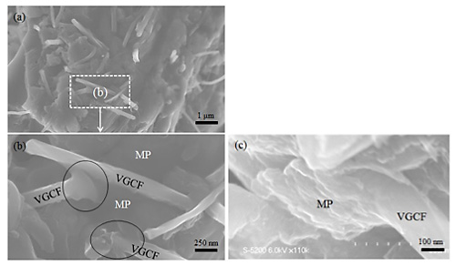
Fig. 3 (a) and (b) show the external appearance of the preform. Most of the MP shows large lumps including VGCFs, whereas very little MP was attached to the VGCF surface. The VGCF edges were well attached at the MP lumps, as indicated by the circle in fig. 3 (b), and the VGCFs were randomly oriented. The MP transformed into a liquid crystalline material when heated in the range 623![]() 773 K and thereafter hardened into so-called "coke". Fig. 3 (c) shows that the MP can grow around the VGCFs when it transforms into coke.
773 K and thereafter hardened into so-called "coke". Fig. 3 (c) shows that the MP can grow around the VGCFs when it transforms into coke.
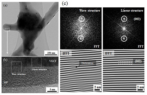
Fig. 4 (a) shows the crosslinked VGCFs by the bridging MP. Moreover, the VGCF surfaces were covered with a thin MP layer, which formed the bridging MP. Fig. 4 (b) shows the VGCF-MP interface, consisting of linear and wavy carbon structures, in the preform. Previous studies shows it is not only linear structure but also wavy carbon structures between the VGCFs. and MP. Fig. 4 (c) shows the results of the interfacial structures between the VGCFs and MP by FFT and IFFT. The wavy structure showed dislocation near the VGCF-MP interface. MP is believed to bridge the VGCFs by combining the free-carbon atoms in MP with the dangling bonds, which are empty valence orbitals on the surface of immobilized atoms, at the VGCF dislocation edges.