Constitutive Modeling of Mechanical Behavior Friction Stir Welded AA2024-T3 Butt Joints:In-plane Tension Tests and Through-thickness Compression tests
The present work examines in-plane tensile and through-thickness compressive stress-strain characteristics of Al alloy 2024-T3 and its butt welds produced by the friction stir welding (FSW) process. FS welded AA 2024-T3 butt joints with 3.18 mm thickness are produced under a fixed set of appropriate welding conditions. A picture of the FS welded joint is shown in Fig. 1. FS welding parameters used are listed in Table 1. Micro-hardness tests are performed to examine the microstructural change occurring during the FSW process (see Fig. 2). In-plane tensile and through-thickness compressive tests on the base material and the FS weld are carried out with an Instron testing machine. Flat tension specimens are machined perpendicular to the weld line of the FS weld (see Fig. 3). Cylindrical compression specimens are machined along the thickness direction of the base material, heat-affected zones and nugget regions in the FS weld (see Fig. 4). The nominal transverse tensile properties of the base material and the FS weld are summarized in Table 2. Constitutive modeling of their in-plane tensile and through-thickness compressive stress-strain behavior is conducted using a rate-independent Ramberg-Osgood equation. Comparison between the measured true tensile stress-strain curves and Ramberg-Osgood plots for the base material and the FS weld in the in-plane transverse direction is given in Fig. 5. Furthermore, comparison between the measured true compressive stress-strain curves and Ramberg-Osgood plots for the base material, heat-affected zones and nugget regions in the through-thickness direction is presented in Fig. 6. It is shown that their tensile and compressive stress-strain curves for the base material and the FS weld can accurately be described by the Ramberg-Osgood constitutive equation, and their tensile stress-strain behavior in the in-plane transverse direction can be predicted from the through-thickness compression data.
[Published in Journal of Light Metal Welding,Vol.50, No.10, (2012), pp.395 -402.]
| Table 1 FSW parameters used for joining AA2024-T3 | |
|
|
| Table 2 Nominal tensile properties of AA2024-T3 base material and FS weld in in-plane transverse direction | |
|
|
 |
 |
|
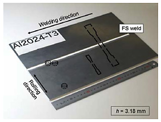
Fig.1 Picture of FS welded AA2024-T3 butt joint with 3.18 mm thickness and locations of specimen extraction |
Fig.2 Microhardness profiles across transverse cross-section of FS welded butt joint and locations at which through thickness compression specimens for weld nugget and HAZ were taken |
 |
 |
|
Fig.3 Geometries of transverse tension specimens. (Top: base material, bottom: FS welded joint) |
Fig.4 Geometries of stacked compression specimens of base material, HAZ and weld nugget |
 |
 |
|
Fig. 5 Comparison between measured true tensile stress- strain curves and Ramberg-Osgood plots for base material and FS weld in in-plane transverse direction |
Fig.6 Comparison between measured true compressive stress-plastic strain curves and Ramberg-Osgood plots for base material, HAZ and weld nugget in through-thickness direction |