Friction stir welding (FSW), developed by The Welding Institute (TWI), has several advantages over the above-mentioned welding technologies, such as lower welding temperature and no fusion welding defects. Therefore, FSW is potentially a practicable joining process for dissimilar materials. FSW normally produces an asymmetric joint due to the fact that metal flow during welding is different at the two sides of the surface through which the tool was plunged, referred to as the advancing side (A.S., where the tool rotation direction is the same as the tool travel direction) and the retreating side (R.S., where the tool rotation is opposite the tool travel direction). Therefore, research into the partitioning metallurgical characterization of the bonded region in a FSWed joint is essential, as the understanding of the superior part of the joint contributes to suitable material design. A number of detailed studies have been reported for joining of an aluminum alloy sheet to a steel sheet by FSW. However, there have been no reports on the investigation of the characterization of individual slices of the bonded region in the FSWed joint. In the present work, the mechanical properties and interfacial microstructure have been evaluated in a FSWed A3003/SUS304 lap joint as a function of lateral offset from the joint axis.
An A3003-H112 aluminum alloy (1.1 wt.% Mn, 0.4 wt.% Fe, 0.2 wt.% Si and 0.1 wt.% Cu) plate with a thickness of 15 mm and a commercial SUS304 plate with a thickness of 12 mm were used in this study. A rotating tool was made of tungsten carbide series material and had a threaded probe with a diameter of 7 mm. The rotating tool was plunged from the A3003 surface onto the surface of SUS304, and lap joints were produced at rotational speeds of 900 rpm and welding speeds of 300 mm/min. A load-controlled type of FSW machine was used in this work. The top of the probe was not inserted into the steel but placed in contact and rubbed just on the surface of the SUS304 in order to prevent pin erosion and overheating. The tool was tilted at an angle of 1.5![]() . A wire-cutting machine was used to prepare a specimen for tensile testing, as shown in Fig. 1. The dimensions of these specimens are also shown. Two specimen types, where the sliced direction is vertical (Fig. 1(a)) and parallel (Fig. 1(b)) to the tool direction, were prepared at 1 mm intervals in order to evaluate the strength in each region after FSW.
. A wire-cutting machine was used to prepare a specimen for tensile testing, as shown in Fig. 1. The dimensions of these specimens are also shown. Two specimen types, where the sliced direction is vertical (Fig. 1(a)) and parallel (Fig. 1(b)) to the tool direction, were prepared at 1 mm intervals in order to evaluate the strength in each region after FSW.
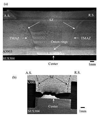
A standard cross-sectional image following FSW is shown in Fig. 2(a). The presence of the stir zone (SZ), thermo-mechanically affected zone (TMAZ), and onion rings were confirmed in the A3003 alloy, as is normally observed in FSWed joints. Fig. 2(b) shows the fracture surface of the specimen sliced vertically (Fig. 1(a)) after being subjected to the tensile test. The broken lines represent the outline of the stir zone. The measured strength is 76.8±0.6 MPa, which is 64% of the strength of the A3003 base alloy (119±7.1 MPa). Around the center region of the specimen, it was found that a fracture occurred in the A3003 alloy matrix, broadening particularly to the advancing side (A.S.). On the other hand, an interfacial fracture occurred in the larger area of the retreating side (R.S.) and on the edge of the specimen.
This fractural distribution became clearer through the tensile test of the parallel-sliced specimen. Fig. 3 shows the tensile strength at each region in the parallel-sliced specimen. We use negative and positive distances from the center of the tool to represent the advancing and retreating sides, respectively. The specimen could not be wire-cut in the region beyond 3 mm from the center because interfacial fracture occurred during wire cutting. Fracture occurred within the A3003 matrix in the specimens cut from the center (0 mm) to the advancing side (-2 mm), and the strength was close to that of A3003 base alloy. On the other hand, the specimens at a distance of 3 mm on the advancing side (-3 mm) and at distances of 2 and 3 mm on the retreating side (2 and 3 mm), fractured at the interface of the specimen.
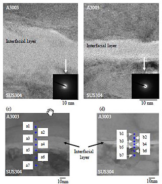
Since the presence of an interfacial reaction layer such as a layer of Al-rich intermetallic compounds could not be observed using a conventional scanning election microscope (SEM) in the obtained joint, TEM observation was carried out at the interface of the joint. Fig. 4 shows HRTEM images of the interface at the center region (Fig. 4(a)) and on the retreating side (Fig. 4(b)), together with the images of the EDX-analyzed spots. In both Fig. 4(a) and (b), nanometer-scale interfacial layers were observed between the A3003 alloy and SUS304. The corresponding diffraction patterns exhibit a halo pattern, identifying these interfacial layers as an amorphous structure. Table 1 lists the EDX analysis results for the region around the interface. Aluminum and iron were enriched within the amorphous layer at the center region (at positions a4 and a5), whereas oxygen was enriched on the retreating side (position b4). It should be also noted that, in the center region, solute atoms composed of SUS304 (iron, chromium and nickel) were detected within the A3003 alloy matrix (at positions a2 and a3), and aluminum was detected within the SUS304 matrix (at positions a6 and a7), whereas the elements of the counterpart materials were barely detected around the interface on the retreating side (at positions b1![]() 3 and b5
3 and b5![]() 7). The processing of the interfacial layer in this work is considered to proceed as follows. First, amorphized aluminum oxide (Al2O3) and steel oxide ((Fe,Ni)CrO4) films, which are originally covered by the alloy surfaces, are stirred by a rotating probe, and a mixed amorphous layer is formed (Fig. 4(b)). During the friction process, the formation of the amorphous layer is most likely produced by kneading, which acts like mechanical alloying of iron on the surface of SUS304 and aluminum (Fig. 4(a)). A longer duration of the friction process would generate more heat input and produce intermetallic compounds. The amorphous layer shown in Fig. 4(a) is most likely the intermediate layer produced before the Al-Fe intermetallic compound is formed.
7). The processing of the interfacial layer in this work is considered to proceed as follows. First, amorphized aluminum oxide (Al2O3) and steel oxide ((Fe,Ni)CrO4) films, which are originally covered by the alloy surfaces, are stirred by a rotating probe, and a mixed amorphous layer is formed (Fig. 4(b)). During the friction process, the formation of the amorphous layer is most likely produced by kneading, which acts like mechanical alloying of iron on the surface of SUS304 and aluminum (Fig. 4(a)). A longer duration of the friction process would generate more heat input and produce intermetallic compounds. The amorphous layer shown in Fig. 4(a) is most likely the intermediate layer produced before the Al-Fe intermetallic compound is formed.
Tensile tests have showed that the strength at the center region and on the advancing side was larger than that on the retreating side, and fracture occurred in the A3003 matrix in the specimen from the center region to the advancing side, whereas fracture occurred at the interface of the specimen on the retreating side. It has been revealed that although interfacial fracture occurs where the Al2O3 and (Fe,Ni)CrO4 oxide films are stirred, the sound joint fracturing at the A3003 base metal is considered to begin to hold when the amorphous layer is formed mainly owing to the mechanical alloying effects of kneading. The strength would be maintained until the thickness of the Al-Fe intermetallic layer reaches approximately 1 ![]() m. Although the joint cut at 3 mm from the center of the tool on the advancing side showed lower strength with interfacial fracture, this is considered to be due to the short stirring duration because the stirring time on the surface of SUS304 under the edge of the probe becomes shorter as the distance from the center of the tool increases. Therefore, it could be concluded that a sound joint can be obtained from the stage of the formation of the amorphous layer owing to the mechanical alloying effects before the formation of intermetallic compounds.
m. Although the joint cut at 3 mm from the center of the tool on the advancing side showed lower strength with interfacial fracture, this is considered to be due to the short stirring duration because the stirring time on the surface of SUS304 under the edge of the probe becomes shorter as the distance from the center of the tool increases. Therefore, it could be concluded that a sound joint can be obtained from the stage of the formation of the amorphous layer owing to the mechanical alloying effects before the formation of intermetallic compounds.