1. Introduction
Sheet metal is used in many industrial fields. A new shearing method has been invented for sheet metal cutting by authors. It has been named MM shearing. In the case of conventional sheet metal cutting by a tool, the sheet metal is cut by vertical movement of the tool in the thickness direction with a shearing machine or press machine. On the other hand, the sheet metal is cut by horizontal movement of the tool in the case of MM shearing. The cutting mechanism is different between conventional shearing and MM shearing in the tool movement direction. There are some important parameters to consider in MM shearing, such as tool angle, clearance between the tool and die, sheet thickness and cutting velocity. The principle and characteristics of MM shearing are described in this paper. A series of experiments was carried out to examine the suitable clearance. The effect of clearance on the cutting force, ratio of sheared and fractured surfaces, inclination angle, burr height, surface roughness and Vickers hardness are discussed, and the mechanism of MM shearing is made clear.
2. Experimental equipment ,workpieces
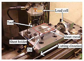
The schematic illustration of MM shearing is shown in Fig. 1. The shaded part of the tool and die is the cutting edge. Firstly, sheet metal is held firmly by the sheet holder and die. When fixed sheet metal is moved in the arrow direction in Fig. 1, it is pushed down in the vertical direction by the tool. The sheet metal which remains between the sheet holder and die is cut by the cutting edge of the tool in the longitudinal direction. On the other hand, the chip is cut by the cutting edge of the die in the vertical direction. The structure of MM shearing is very simple in that it uses only a tool, sheet holder and die besides the moving apparatus. The present paper focuses upon the effect of clearance Cl, which was defined as the distance between the tool and die edges as shown in Fig. 1. A photograph of the experimental set-up is shown in Fig. 2. A milling machine is used for feeding the sheet metal in the horizontal direction. When the sheet metal is cut, horizontal and vertical cutting forces act on the tool edge. The horizontal cutting force Fh and vertical cutting force Fv are measured by two load cells as shown in Fig. 2.
In the present study, the tool angle was set at either 25 or 45 degrees, which are within the suitable range found in the previous research. The material of the tool, sheet holder and die are die steel SKD11 (JIS, Japanese Industrial Standard). The length of tool Sl was 16.0 mm, and the width of tool Sw was 3.2 mm. The experimental material of the sheet metal was A1100 (JIS), of which tensile strength ![]() B was 138 MPa, and total elongation was 16%. The length l of the test piece of sheet metal was 80 mm, the width w was 60 mm, and the thickness was 1.5 mm. The cutting velocity vs was a constant 170 mm/min. The clearance of the tool and die was from 0 to 0.3 mm. Experiments were carried out in order to clarify the effect of clearance. The experimental conditions are summarized in Table 1.
B was 138 MPa, and total elongation was 16%. The length l of the test piece of sheet metal was 80 mm, the width w was 60 mm, and the thickness was 1.5 mm. The cutting velocity vs was a constant 170 mm/min. The clearance of the tool and die was from 0 to 0.3 mm. Experiments were carried out in order to clarify the effect of clearance. The experimental conditions are summarized in Table 1.
3. Experimental Result and Discussion
Fig. 3 shows the effect of clearance on cutting forces Fh and Fv. The vertical cutting force Fv was almost constant regardless of clearance Cl. The horizontal cutting force Fh was larger when clearance Cl was less than 0.1 mm. The reason can be described that a decrease of clearance Cl increases the area fraction of the sheared surface, which leads to an increase of cutting force Fh.
Fig. 4 shows the effect of clearance on the area fraction of sheared and fractured surfaces. The cut
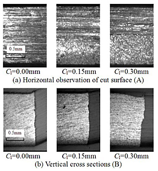
surfaces with tool angle ![]() of 25 degrees and 45 degrees together consisted of only sheared surfaces when clearance Cl was 0. With the increase of clearance Cl, the area fraction of the fractured surface increased and the area fraction of the sheared surface decreased. The area fraction of the fractured surface reached about 65% in the case with clearance Cl of 0.3 mm. Fig. 5 shows the cut surface and cross section with tool angle
of 25 degrees and 45 degrees together consisted of only sheared surfaces when clearance Cl was 0. With the increase of clearance Cl, the area fraction of the fractured surface increased and the area fraction of the sheared surface decreased. The area fraction of the fractured surface reached about 65% in the case with clearance Cl of 0.3 mm. Fig. 5 shows the cut surface and cross section with tool angle ![]() of 25 degrees. When clearance Cl is 0, the initial crack which appeared around the die cutting edge did not continue during shearing. Thus, the cut surface consisted of only a sheared surface. On the other hand, the crack from the die cutting edge appeared earlier when clearance Cl was large. As a result, with the increase of clearance Cl, the area fraction of the fractured surface increased, and the area fraction of the sheared surface decreased. This tendency has also been observed in the result with tool angle
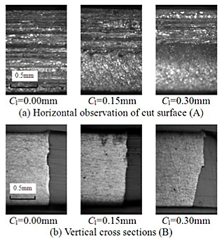
of 25 degrees. When clearance Cl is 0, the initial crack which appeared around the die cutting edge did not continue during shearing. Thus, the cut surface consisted of only a sheared surface. On the other hand, the crack from the die cutting edge appeared earlier when clearance Cl was large. As a result, with the increase of clearance Cl, the area fraction of the fractured surface increased, and the area fraction of the sheared surface decreased. This tendency has also been observed in the result with tool angle ![]() of 45 degrees as shown in Fig. 6.
of 45 degrees as shown in Fig. 6.
4. Conclusion
A new shearing method for sheet metal with horizontal tool movement was named MM shearing invented by Dr. Murata. The effect of clearance on cutting force, cut surface, burr height, surface roughness and so on were examined by experimental method.