The mechanical properties of a functionally graded aluminum (FG) foam can be controlled at desired locations by varying the pore structures and the types of aluminum alloys in the same aluminum foam. However, there have been few reports on the compressive properties of FG foams due to the difficulties of controlling the pore structures (i.e. porosity and pore size) in a single foam. In this research, an FG foam varying pore size and porosity was fabricated using aluminum alloy die castings contained a large amount of gas by friction stir processing (FSP), and the compressive properties of the FG foam was examined.
Figure 1 shows a schematic illustration of the fabrication process of the FG foam precursor. As starting materials, Al-Si-Cu aluminum alloy ADC12 die casting plates were used. TiH2 powder ( < 45![]() m, 1 mass%) as the blowing agent and Al2O3 powder (
m, 1 mass%) as the blowing agent and Al2O3 powder (![]() 1
1 ![]() m, 5 mass%) as the stabilization agent were both used for one of the laminated plates (Fig. 1(a)) and only Al2O3 powder was used for the other laminated plates (Fig. 1(a')). The multipass FSP technique was applied to obtain large precursors and to mix the gases and powders thoroughly (Fig. 1(b)
m, 5 mass%) as the stabilization agent were both used for one of the laminated plates (Fig. 1(a)) and only Al2O3 powder was used for the other laminated plates (Fig. 1(a')). The multipass FSP technique was applied to obtain large precursors and to mix the gases and powders thoroughly (Fig. 1(b) ![]() (f) and Fig. 1(b')
(f) and Fig. 1(b') ![]() (f')). The obtained laminated plates were cut in the stirred region (Fig. 1(g) and (g')), and these plates were butt-welded by conducting friction stir welding (FSW) on both sides (Fig. 1(h) and (i)). A precursor sample was cut from the stirred region including the bonding interface and then heated in a preheated electric furnace. The compression specimens of 15 mm
(f')). The obtained laminated plates were cut in the stirred region (Fig. 1(g) and (g')), and these plates were butt-welded by conducting friction stir welding (FSW) on both sides (Fig. 1(h) and (i)). A precursor sample was cut from the stirred region including the bonding interface and then heated in a preheated electric furnace. The compression specimens of 15 mm![]() 15 mm
15 mm![]() 30 mm were cut by electro- discharge machining from the foamed samples. The porosity p of the fabricated two compression specimens was p=77.8% and p=77.6%. The pore structures in the compression specimens were observed by X-ray CT nondestructively. Compression tests were carried out at room temperature using the universal testing machine at the strain rate of 3.3
30 mm were cut by electro- discharge machining from the foamed samples. The porosity p of the fabricated two compression specimens was p=77.8% and p=77.6%. The pore structures in the compression specimens were observed by X-ray CT nondestructively. Compression tests were carried out at room temperature using the universal testing machine at the strain rate of 3.3![]() 10-3 s-1.
10-3 s-1.
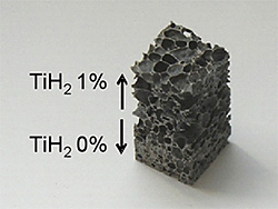
Figure 2 shows the FG foam compression test specimen with p=77.8%. Two layers can be seen, a 1% TiH2 layer (upper layer) and a 0% TiH2 layer (lower layer), with different pore structures. Figure 3 shows the relationship between the location of the specimen (compression direction) h, which was normalized by the height of the specimen, and the porosity which was evaluated from X-ray CT images. In this figure, the representative X-ray CT images for both layers were also shown. It can be seen that each layer has almost constant porosity, and the upper layer has higher porosity than the lower layer. This tendency was also observed for the diameter and sphericity of the pores. Consequently, it was revealed that FG foam with different pore structures existing in a single aluminum foam can be obtained. Note that the porosity (and pore size) changed gradually at the bonding region (around h=25% - 40%). This is considered to be due to the dispersion of blowing agent during the bonding process by FSW, and it was shown that a seamless FG foam can be fabricated.
Figure 4(a) shows typical stress-strain curves for the FG foam (p=77.8%, red solid line), along with those of uniform ADC12 aluminum foam with 1% TiH2 added (p=88.3%, green solid line) and uniform ADC12 aluminum foam without TiH2 (p=71.2%, blue solid line). Figure 4(b) ![]() (g) show sequential deformation images of the FG foam. As can be seen from these images, the FG foam first started to deform only in the upper layer, and little deformation could be seen in the lower layer up to approximately 50% strain; thereafter, the lower layer started to deform. To enable the direct comparison of the stress-strain curves between the FG foam and the uniform foams, the strain of the uniform foam with 1% TiH2,
(g) show sequential deformation images of the FG foam. As can be seen from these images, the FG foam first started to deform only in the upper layer, and little deformation could be seen in the lower layer up to approximately 50% strain; thereafter, the lower layer started to deform. To enable the direct comparison of the stress-strain curves between the FG foam and the uniform foams, the strain of the uniform foam with 1% TiH2, ![]() , at the compression strain
, at the compression strain ![]() =0% - 50% in Fig. 4(a) was modified as
=0% - 50% in Fig. 4(a) was modified as
| (1) |
where hu and h0 are the length of the upper layer and the entire height of the specimen. Similarly, the strain of the uniform foam without TiH2, ![]() , at
, at ![]() =50% - 70% was modified as
=50% - 70% was modified as
| (2) |
where hl is the length of the lower layer. The modified stress-strain curves were indicated in Fig. 4(a) with dotted lines. It was shown that first and second plateau regions appeared independently in the FG foams, and they were corresponding to the each plateau regions appeared in the each uniform foam. In addition, the stress-strain curves indicated seamlessly from first plateau region to second plateau region around ![]() =50%. This is assumed to be the seamless bonding of two types of foams, because pore structures were gradually changing at the bonding interface as shown in Fig. 3.
=50%. This is assumed to be the seamless bonding of two types of foams, because pore structures were gradually changing at the bonding interface as shown in Fig. 3.
In this study, an FG aluminum foam varying pore structures was developed and the compressive properties of the obtained FG foam were demonstrated. It was shown that the FG foam has two different deformation stages and two plateau regions with a seamless bonding interface.